| 1 |
| |
|
|
|
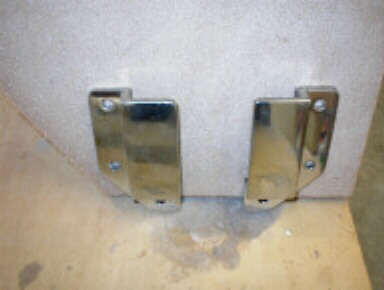
Stainless steel brackets that will house the lock and brake away key, on
the rudder. This key will shear if hit hard enough or may be removed
to lift the rudder when needed. Spare keys will be on board and the
pattern will be here at Pedigree if more are needed. |
|
|
| 2 |
| |
|
|
| |
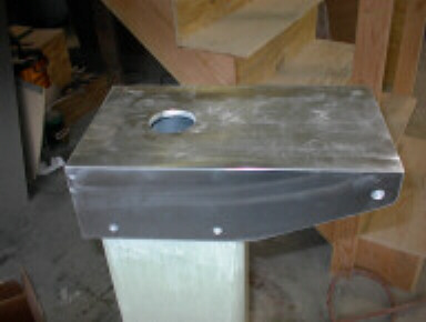
Top hinge assembly of the rudder tilt mechanism. The hole in the top
allows the rudder shaft to protrude enough to install the steering arm and
allow an emergency handle to be fastened.
|
|
|
| 3 |
|
|
|
|
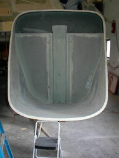
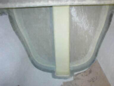
This shows how the rudder assembly fits into its housing and also shows how
wide the slot in the steps would have to be.
|
|
|
| 4 |
| |
|
|
| |
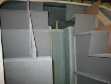
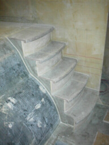
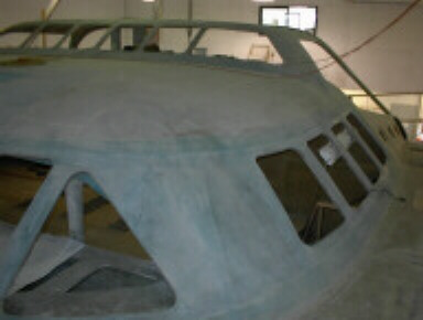
A new step design emerging that will allow flush steps with no visible slots
to step in.
|
|
|
| 5 |
| |
|
|
| |
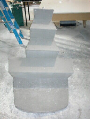
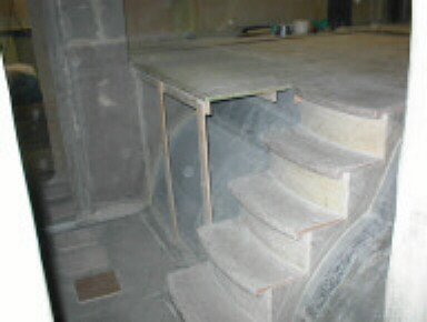
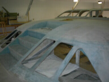
This is the section of steps that will raise with the rudder. This design
allows all steps to be continuous with out a wide slot left open when the rudder
is down. |
|
|
| 6 |
| |
|
|
| |
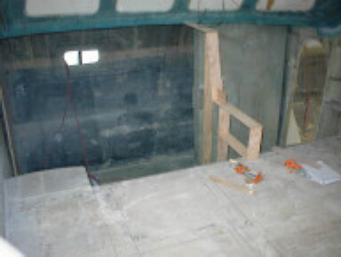
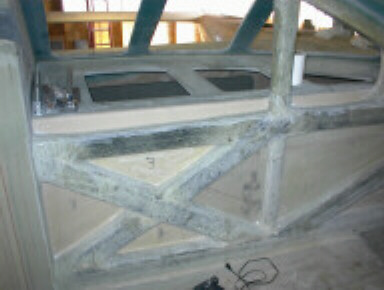
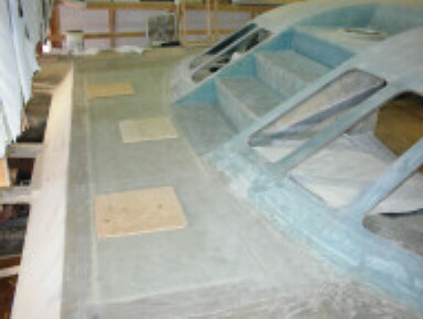
This is the back side of the rudder bulkhead as viewed from the engine room.
|
|
|
| 7 |
| |
|
|
| |
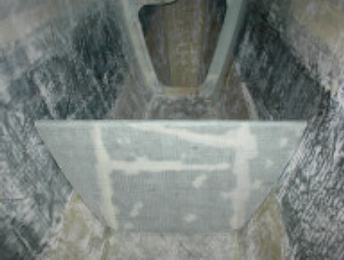
Alternate view.
|
|
|
| 8 |
| |
|
|
| |
Steps down into port hull.
|
|
|
| 9 |
| |
|
|
| |
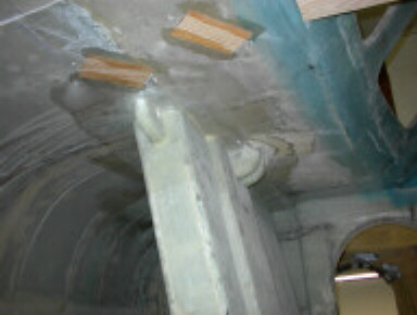
This view, is of the top of the dagger board case. It shows the molded
housings for the up and down pulleys and the hard spots being installed for
the through bolting of the turning deck pulleys which will route the lines
back to the cockpit winch. |
|
|
| 10 |
| |
|
|
| |
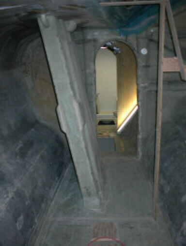
A view forward, on the port side, taken from the steps of the salon.
|
|
|
| 11 |
| |
|
|
| |
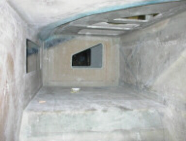
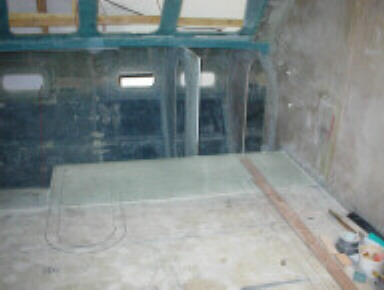
A view in the port forward berth. The cut outs at the top will have
frosted and tinted, tempered glass installed to allow more light into this
area from the front main cabin windows. A book shelf is on the left
and at the end, an access to a very large compartment for storage. |
|
|
| 12 |
| |
|
|
| |
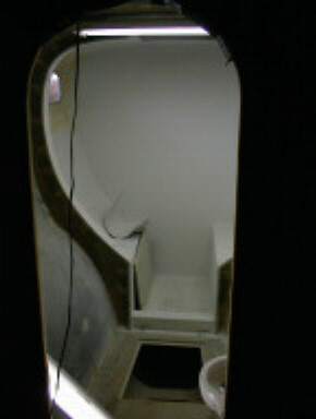
Another view of one of the showers, ready for new color coat. This
will have an etched patterned, clear acrylic, font door and side panels.
|
|
|
| 13 |
| |
|
|
| |
Galley floor has been extended and the layout has been started. Looking
starboard, from the center of main salon. |
|
|
| 14 |
| |
|
|
|
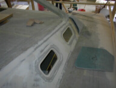
This shows the cut out above the forward births for the light panels.
|
|
|
| 15 |
| |
|
|
| . |
The steps coming down into the starboard hull and the galley floor extension
shown. |
|
|
| 16 |
| |
|
|
|
The aft cabins are shipping up with the additional ram air intake for the
engines.
|
|
|
| 17 |
| |
|
|
|
Wide angle lens would be nice.
|
|
|
| 18 |
| |
|
|
|
Alternate View.
|
|
|
| 19 |
| |
|
|
| |
Front deck ready for hatches.
|
|
|
| 20 |
| |
|
|
| |
This bin is for the anchor line and chain to drop into. The primary
systems will have 3/8" chain and 3/4" line, totaling 300' of scope. This give
10 to 1 scope for hurricanes in 30' of water. Also placed in these
lockers will be extra rode, lengths of 100' and 200' and Viking aluminum anchors. |
|
|